
Product Portfolio
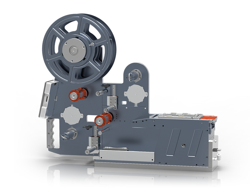
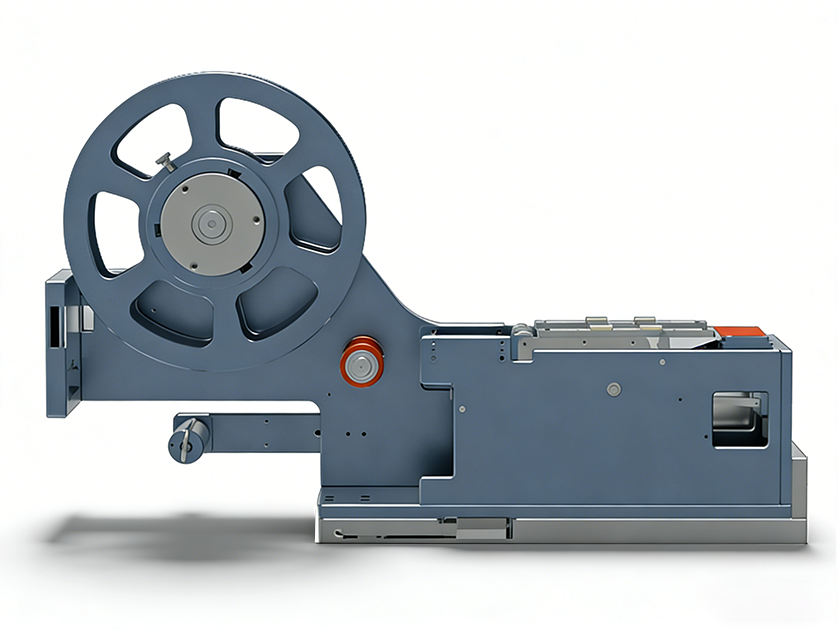



ARD-LBC
60-51-***-028-L-V4.0
Standard cutting feeder
High-precision variable-length cutting

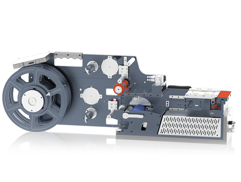
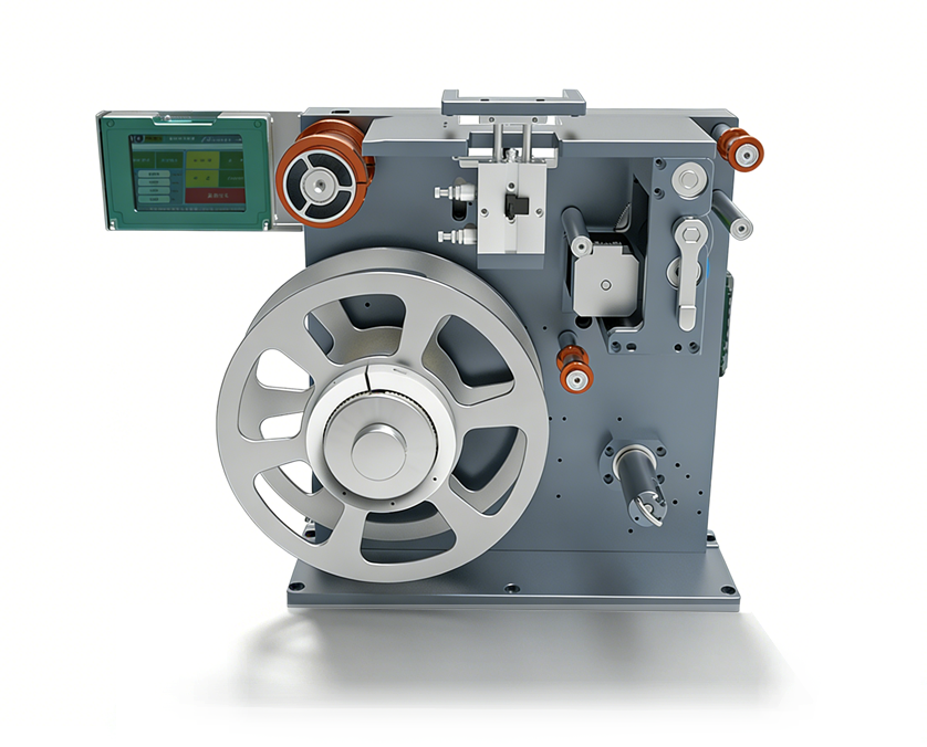
ARD-LBC
40S300-L170-L-C1-V2.0
Single-sided adhesive cutting feeder
With liner film recovery

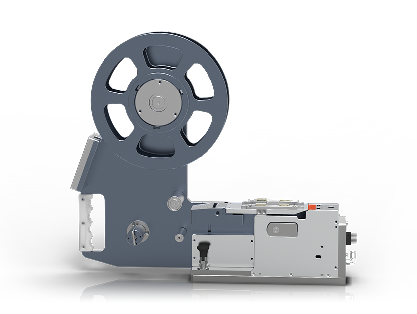
ARD-LBC
040S185-L050-R-C2-V2.0
Special material cutting
Fast pull-out with precise fixed-length cutting

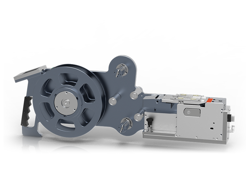
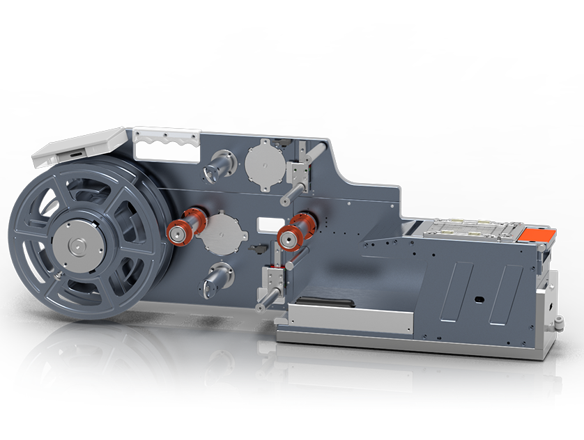
ARD-LBC
060XP-L0220-W0220-V4.0
Solder preform cutting feeder
Dedicated to cutting solder preforms (solder ribbons) for IGBT


Application Scenarios
Feeding Principle
Key Advantages
High cutting precision, adjustable cutting length, suitable for a variety of materials, and a high degree of automation.
Limitations
High requirements for the flatness and stability of the material; the cutting tools need regular maintenance.
Required Parameters
1、Cutting length
2、Cutting precision (±0.5mm)
3、Material thickness
4、Cutting speed
5、Incoming material: single-sided tape / double-sided tape
Basic Requirements
• The material must have good cutting performance;
• The material thickness must be uniform, without any variation;
Solder Preform Cutting Feeder Intro
The solder preform cutting feeder is an automated device specially used for producing power semiconductors (IGBT). The cutting specification can be adjusted according to the wafer size, and it can also die-cut solder preforms sized for soldering capacitors and resistors (feed length of about 0.8mm). At present, mainstream solder ribbons are mainly tin-based solder ribbon and lead-based solder ribbon.
Working Principle
Working principle: Through sensors and internal structures, a high-speed and high-precision closed-loop "feeding-cutting" process is realized, precisely controlling the conveying and cutting of roll solder ribbon. Multi-specification feeders adapt to solder ribbons of different specifications.
Parameter Details
Parameter details: cycle time: 0.2-0.3s/p, precision: ±0.07mm, applicable cutting specifications: 0.5≤L≤20, 1≤W≤20, host computer communication: RS232, touch screen display control, product weight: about 9KG, rated power supply: 24V DC 8.0A
Nozzle Sensor Version Working Principle
Nozzle sensor version working principle: The nozzle moves down and blocks the through-beam fiber optic light source, triggering a nozzle-in-position signal that controls the lower cutting blade to rise and cut the material. After the nozzle takes away the cut material, the light received by the fiber optic returns to normal, triggering a nozzle-leave signal that controls the feeding assembly to continue feeding.
Nozzle Sensor Version Advantages
Advantages: The feeding stroke and cutting action are controlled by a microcontroller, providing stable output and high cutting precision. Ample space allowance suits materials of different specifications, and any length can be cut (including lengths within 2mm).
Vacuum Suction Version Working Principle
Vacuum suction version working principle: When the material is in position, the fiber optic determines that feeding is complete and gives feedback; the vacuum turns on to hold the material, then the lower cutting blade performs the cutting; after cutting is completed, the vacuum turns off and waits for the nozzle to take away the material; the fiber optic determines that pick-up is complete and gives feedback, and the feeding assembly continues feeding. When the fiber optic determines that feeding is in position again, the next cutting cycle begins.
Vacuum Suction Version Advantages
Advantages: In the vacuum version, the next cutting cycle can begin immediately after the nozzle takes away the material, offering higher cutting efficiency. The feeding stroke and cutting action are controlled by a microcontroller, providing stable output and high cutting precision, with timely feedback on whether the material has been taken away. Ample space allowance suits materials of different specifications.